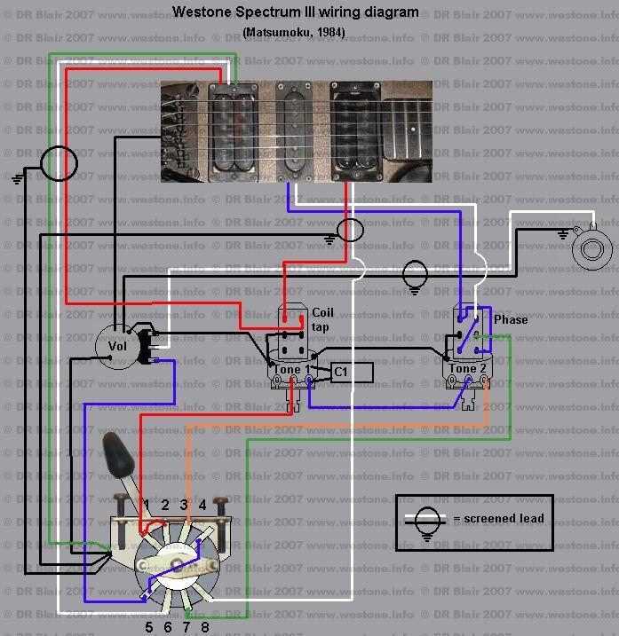


| Switch position | Pickup selected | Contacts connected |
| 1 | Neck | (1/2),(4/5),8 |
| 2 | Neck/Centre | (1/2),(4/5),7,8 |
| 3 | Centre | (1/2),(4/5),7 |
| 4 | Centre/Bridge | (1/2),3,(4/5),6,7 |
| 5 | Bridge | 3,(4/5),6 |
| Switch contacts 1 and 2 are permanently connected by a wire link as shown, contacts 4 and 5 are also connected together by a wire link. In the wiring diagram, the switch lever is in position 1. | ||